Why ESP32 Breadboard Builds Fail Even When the Wiring Looks Correct
Your ESP32 isn’t broken. If a breadboard build behaves inconsistently, the fault is often physical, not firmware. This article explains how breadboard construction creates electrical instability that looks like software failure.
The familiar failure pattern
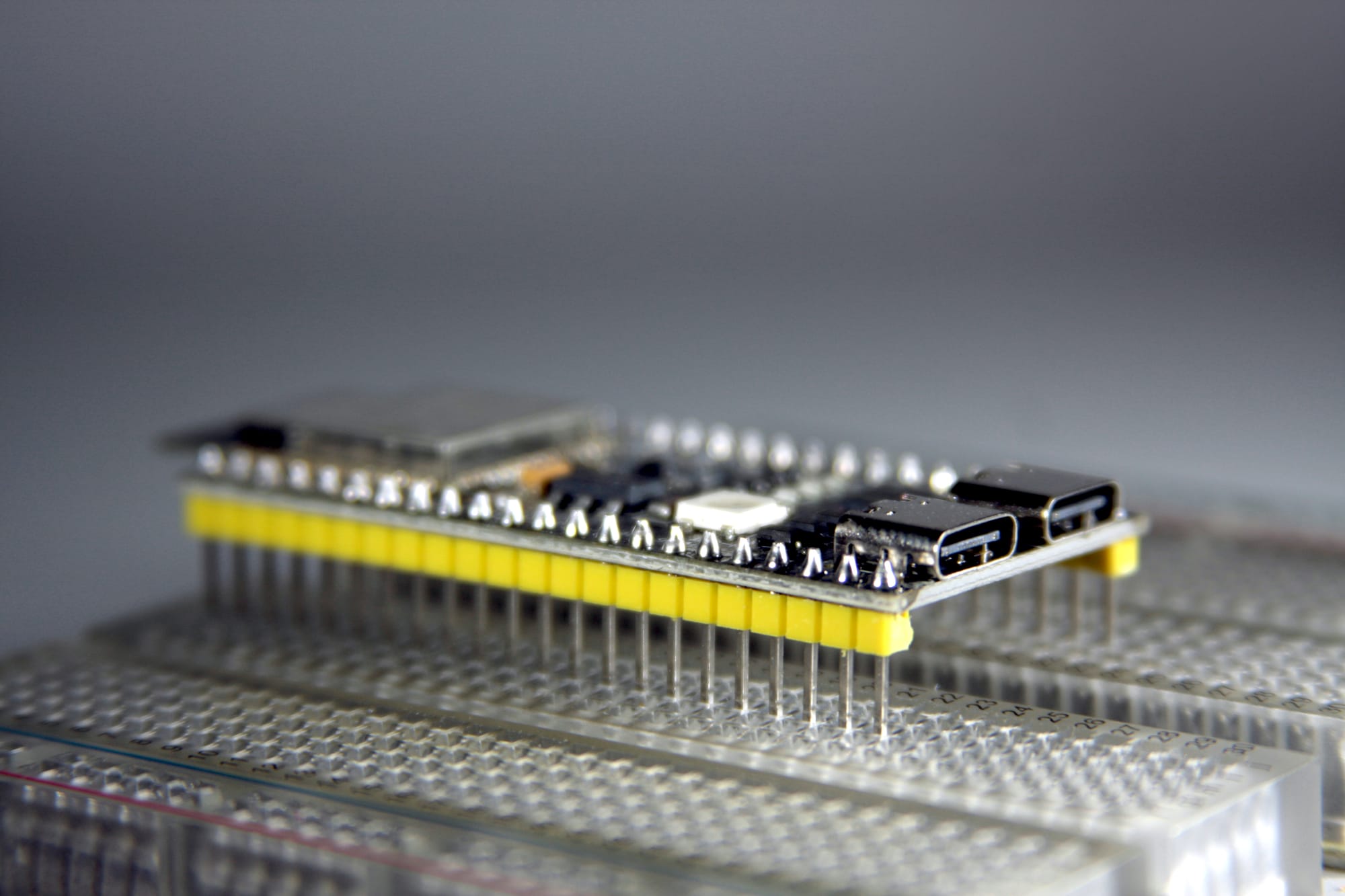
The build looks clean, all jumper wires are connected and the ESP32 Dev board sits on the breadboard like it belongs there. You connected the power rails and the I2C LCD lights up and shows the correct text which you expected.
Then something happens and the line of characters turns to hieroglyphs (random broken characters), freezes, or the text disappears entirely. Another time the system resets unexpectedly when a jumper wire is touched or the breadboard gets moved slightly.
You tried to reflash the firmware – at first it looked like it helped, then it happened again.
I spent quite a while observing and analyzing what could be the cause, and this was the spark to write this article. It may help others too.
If you've built more than one ESP32 project on a breadboard, you may have seen this and probably figured it out on your own, but I'm going to explain it to those who may still struggle or wish to understand better why.
Why this feels random
All jumper wires are connected according to the schematics or whatever reference you're working from. The firmware source code has no major errors. The ESP32 Dev board itself functions normally. The behaviour feels random and unpredictable because the cause is physical and not logical.
Breadboards are often treated as neutral bases to hold components, like electrically neutral scaffolding. In practice, they're mechanical systems with electrical consequences. Those consequences are critical in some circumstances. Breadboards have unreliable connections that fluctuate.
A visually sound connection on a breadboard isn't connected or disconnected—it drifts between acceptable and marginal conditions. That drift happens on a timescale fast enough to affect digital logic but slow enough to escape visual inspection.
Definitions used in this article
- Breadboard tie point: A spring-loaded metal contact inside a breadboard that grips a pin or wire (the holes where you insert component legs or jumper wires).
- Contact resistance: Resistance introduced by imperfect physical contact between conductors
- Ground reference: The shared 0V reference point used to measure voltages and interpret logic levels
- Transient load: A short-duration current demand caused by internal activity
- I2C bus: A two-signal (two-wire) serial communication bus using SDA (data) and SCL (clock). Devices also require power and ground, which are separate from the bus signals but critical for correct operation.
What actually fails electrically
A breadboard connection relies on spring tension pressing against a metal pin. That pressure varies based on:
- Pin diameter
- Insertion depth
- Contact wear
- Oxidation
- Side load from attached wires
- Environmental factors like vibrations and even temperature.
The resistance of each connection is neither zero nor stable.
When current flows through a connection with variable resistance, the voltage across it varies. These variations are often brief and small, but digital systems operate within tight margins.
A few microseconds of power supply dip or ground shift can change how a signal is interpreted. This is why breadboard faults rarely appear as clean disconnects. Instead, you get partial contact, momentary resistance spikes, and shifting reference levels. Visually, the wire remains inserted, but electrical conditions fluctuate.
Why ESP32 exposes the issue
When a breadboard project contains ESP32 Dev boards, the circuit becomes more prone to visible errors.
Three factors matter:
- Current bursts: The ESP32 draws current in bursts due to wireless activity and internal regulators.
- Startup timing: The ESP32 samples critical signals during startup, which can be disrupted by supply or ground movement.
- Timing-sensitive buses: I2C assumes a stable supply, clean edges, and a shared ground reference.
Breadboard projects expose all three. The ESP32 doesn't create these problems—it only reveals them. Slower systems often tolerate this instability because they have longer timing margins and lower switching speeds. The ESP32 does not.
Why displays and sensors show it first
Power supply issues: Character LCDs with I2C backpacks often reveal breadboard instability early and more often because their controllers expect stable electrical conditions. A brief supply dip can place the controller into an undefined internal state. Internal memory may corrupt without any obvious restart.
Bus signal issues: On the bus side, momentary resistance changes on SDA or SCL can truncate transactions. The ESP32 completes the transfer, but the signal doesn't reach the display and gets interrupted.
Ground reference issues: Ground reference movement is subtler but equally disruptive. If devices briefly disagree on logic thresholds, bits flip without any wire fully disconnecting.
This produces recognisable symptoms:
- Random glyphs in otherwise correct text
- Displays freezing mid-update
- Backlights flickering independently
- Correct behaviour after reset followed by gradual corruption
These are electrical side effects of unstable construction, not software or component faults.
Hot tip
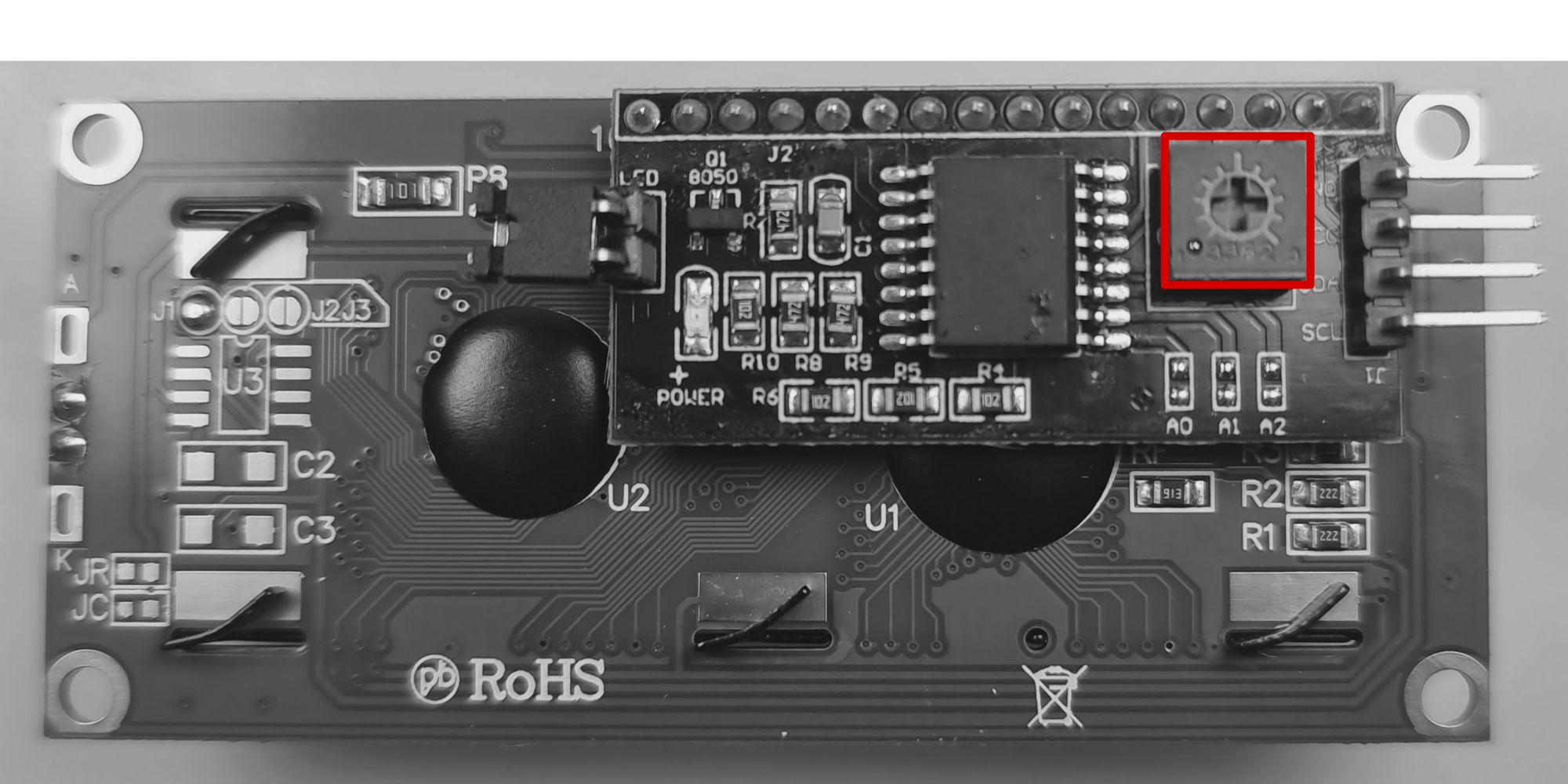
Many I2C LCD backpacks include a small contrast trimmer potentiometer. When this is set to one extreme, which is common from the factory, the backlight turns on but no characters are visible, even though communication is working.
Turn the potentiometer slowly while the display is powered until characters become visible. Check this before debugging wiring or firmware.
Common symptoms to watch for
Breadboard instability tends to follow a pattern:
- The system works initially, then degrades.
- Behaviour changes when the board moves.
- A reset temporarily restores function.
- Reflashing firmware has no lasting effect.
- Adding a single peripheral destabilises the build.
Diagnosing the cause without tools
An oscilloscope would be helpful, but not everyone has one sitting on the kitchen table—I don't. In my past working environment I had access to one in the workshop, but as a hobby DIYer at home it's always been a dilemma whether to get one or not. Probably one day, especially as this hobby seems to be edging toward production level.
Simple controlled changes often confirm the source:
- Lightly tap the desk and watch the display.
- Gently nudge a jumper wire and observe changes.
- Tilt the board slightly and note whether behaviour shifts.
Another effective test is substitution. Replace only the power and ground jumpers with solid-core wire while leaving everything else unchanged. If stability improves, the cause is physical rather than logical.
Equally important is knowing what doesn't help. Adding debug prints, logic analysers, or rewriting code rarely changes the behaviour when the fault is mechanical.
When behaviour changes with mechanical conditions, the failure is mechanical, even when it appears digital.
What improves stability
Solid-core wire is not a feature for a YouTube vid to look nice—it has deeper reasons than that. It fills the breadboard tie-point better, increases pressure, and reduces movement. Shorter, stiffer wire runs reduce leverage at contact points. Shared, direct ground paths reduce reference drift.
In electrical terms, this stabilises:
- Supply voltage under transient load.
- Signal edge timing.
- Ground reference consistency.
The circuit logic remains unchanged, but the system stops operating near its tolerance limits.
This explains why using solid-core wire improves breadboard builds so much—it can stabilize even sensitive components like LCDs. Further construction details deserve deeper treatment and are best covered in a separate article.
How reliability progresses
A useful way to think about reliability is as a progression:
- Pre-made jumper wires on a breadboard
- Solid-core wire on a breadboard
- Perfboard or stripboard
- PCB with connectors
- Fully soldered, strain-relieved connections
Each step removes a source of variability and makes faults easier to reason about.
Breadboards are effective learning tools for rapid prototyping. Treating them as electrically neutral leads to misplaced blame and unnecessary frustration.
Closing perspective
When an ESP32 build behaves unpredictably, it's tempting to doubt your understanding or assume the platform itself is unreliable.
In many cases, neither is true.
The circuit is correct.
The firmware behaves as written.
The problem lies in how the system is physically held together.
Once construction quality is treated as part of the design, these failures become easier to recognise and easier to resolve. That understanding carries forward into every future build.